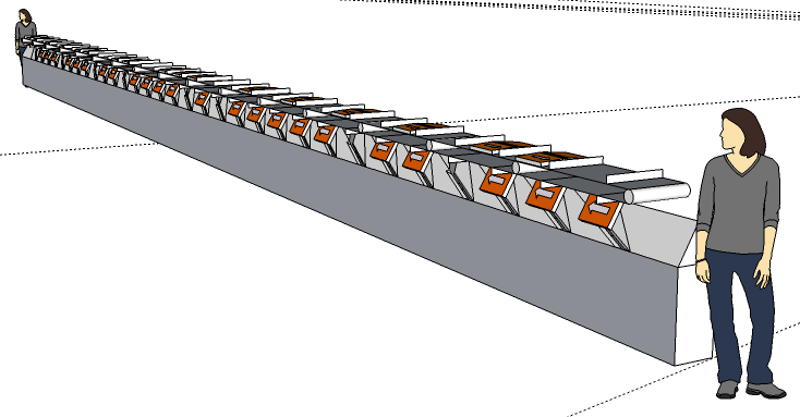
Prototype 1 Design
Overview
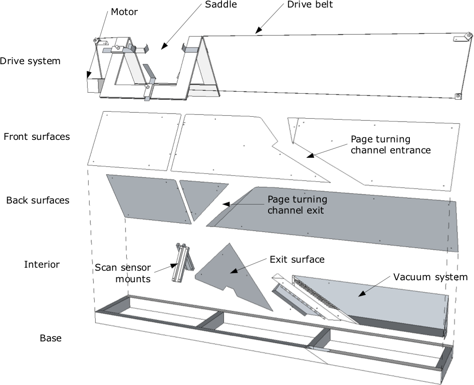
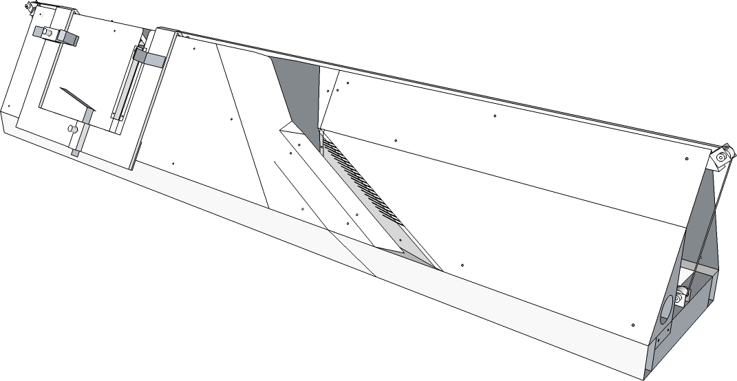
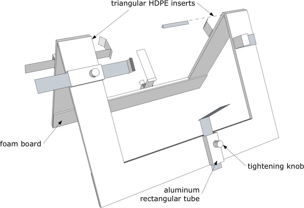
The machine’s frame is built primarily from sheet metal, with a base of rectangular metal tubing. The book is held in a “saddle” which is driven back and forth by a stepper motor. The book moves over linear sensors to capture images, and across a page turning channel which turns a page on each pass. A vacuum connects at one end and provides both suction and exhaust to separate pages.
Drive system
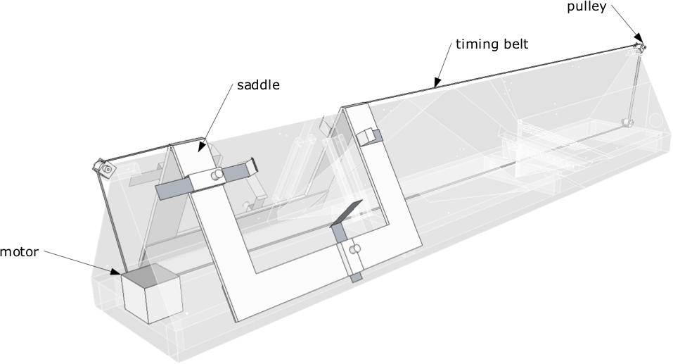
The saddle is attached to a timing belt which passes around and through the machine. The motor is a stepper motor with built-in microcontroller, and it is programmed to move the saddle back and forth repeatedly.
The saddle is made from clear acrylic, and has adjustable “clamps” to hold the book in place. These clamps should be adjusted to each book before scanning. They are not meant to hold the book tightly, but the lower clamps help support the weight of the book when most of the pages are to one side or the other.
Vacuum system
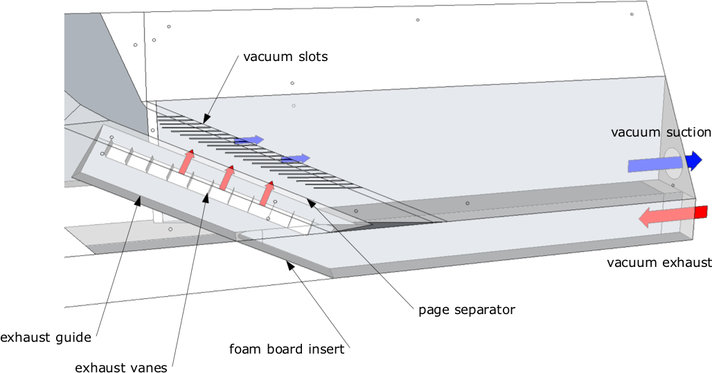
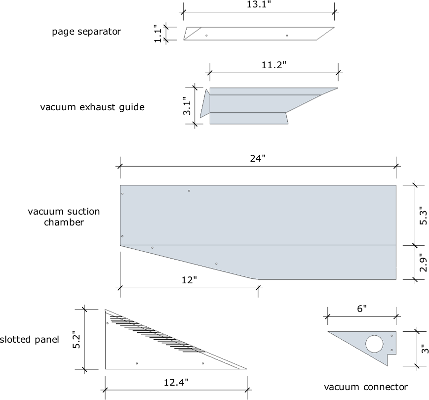
Air is sucked through an array of vacuum slots to pull a single page into the page turning channel. The page separator is an edge which divides the page being turned from the rest, as the book travels from right to left.
Vacuum (shown in blue) is applied to a chamber behind the slots, and the vacuum exhaust (red) is routed back into one end of the base. The exhaust is channeled out behind the page separator to blow against the edge of the turned page, to help separate pages that are stuck together.
Design Notes
The following are various considerations to note in the design of the prototype.
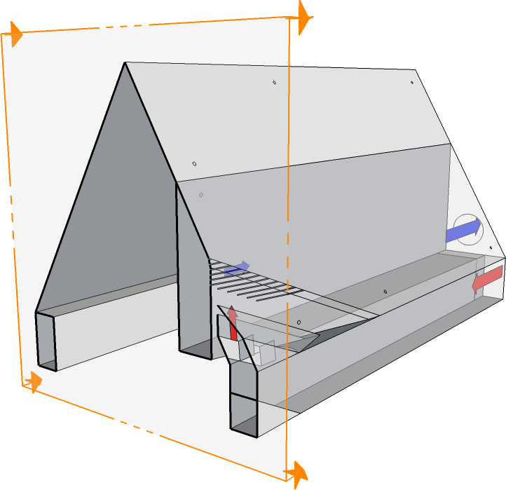
Overall dimensions
The prototype is 5 feet long, providing enough room for the page turning channel, plus a book length on either end, allowing the book to completely clear the channel. The main body is a triangular prism, 10 inches on each side. The 10” dimension constrains the size of books that can be scanned, as the book must fit over the machine without extending past the sides.
The angle at the apex is 60 degrees. If this angle is too small, the sharp apex may cause damage to the spine, and there will also be less room for scan sensors to reach into the gutter of the book. If the angle is too large, then books will not lay flat against the machine, and the gutter of the book will not be visible to the sensors.
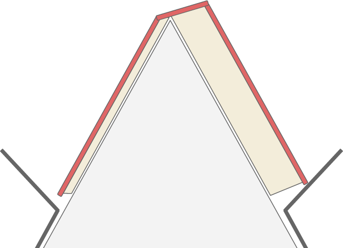
Apex alignment
Along the apex of the machine, two surfaces meet to form an edge. To ensure smooth motion, one of these surfaces is usually tucked under the other like this (end view):

The following top view of the machine indicates where one surface is tucked under the other:
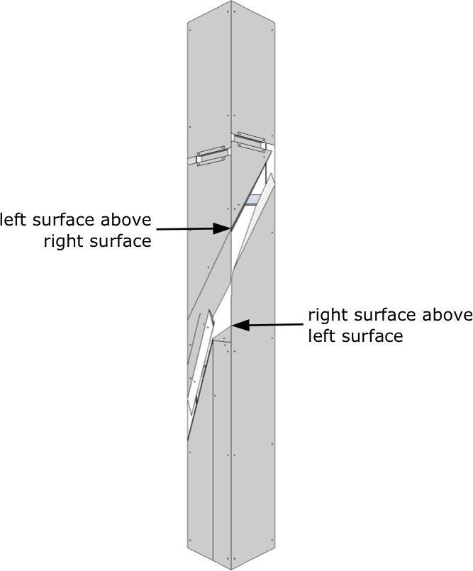
At these two locations, there is a transition from one surface supporting the spine of the book to two surfaces. The surface which is introduced should be tucked under the other to ensure that the book rides smoothly over the transition.
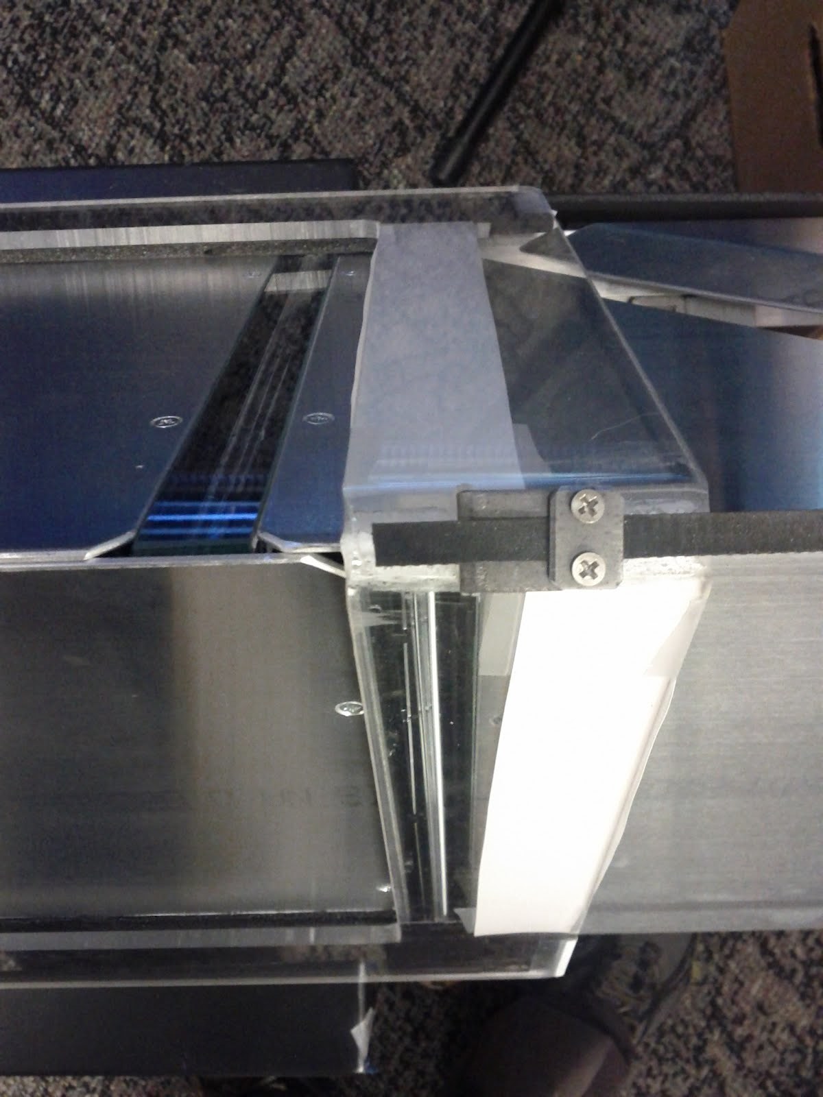
Vacuum slots
The bending angle and curvature of the vacuum slot area determines how the page to be turned is pulled away from the rest. If the curvature is too low and the turned page does not bend much, then pages are likely to stick together when turning. If the curvature is too high, then thick pages may not turn at all. The radius of curvature in the prototype is approximately 1/2 inch.
Page separator
The page separator is the surface which divides the turned page from the rest immediately after encountering the vacuum slots. The leading edge of the page separator must be recessed into the machine, or other pages might droop down and enter the page turning channel as well. Behind the page separator is an exhaust channel which blows air over the edge of the turned page to help separate any pages that are stuck together. This exhaust channel must be tucked far enough behind the page separator that the turned page does not snag against it.
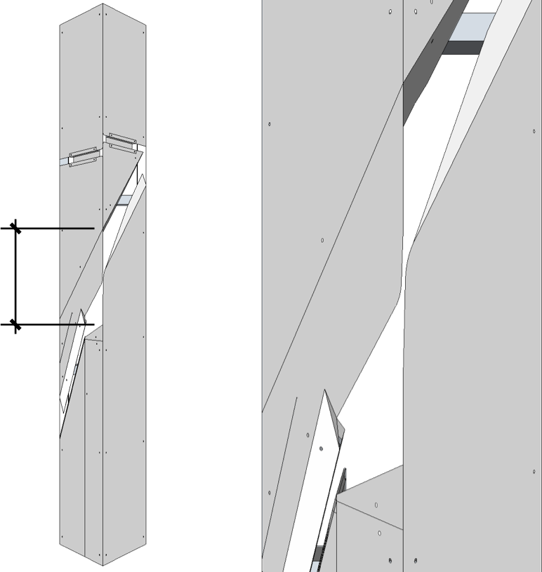
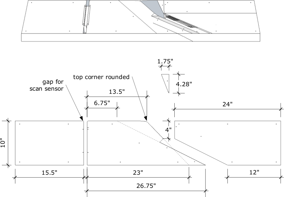
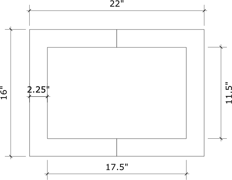
Dimensions of vacuum section
The dimensions of the vacuum section create constraints on the book sizes that can be scanned. This diagram shows the front panel adjacent to the vacuum slots. The vacuum area is in blue:

In the diagram, dotted lines are extended along the slope of the vacuum section and the top edge of the machine, forming a right triangle (ABC). The page being turned will curve along the slope of the vacuum section and this curve follows line “C” as the book travels from right to left. If the “A” dimension of this imaginary triangle is much shorter than the spine of the book, then the curve of the page will put pressure on the binding where “A” and “C” meet, and may cause the page to rip. So, the “A” dimension limits the height (spine length) of books that can be scanned. To maximize this dimension, the vacuum section and the “C” line should have a shallow slope. But note that a very shallow slope requires the machine to be longer overall, and the book to travel farther. In the prototype, the slope is 1/2.
Also, the “B” dimension is a lower bound on the width of books that can be scanned, because the book must be at least that wide to reach the vacuum slots at all.
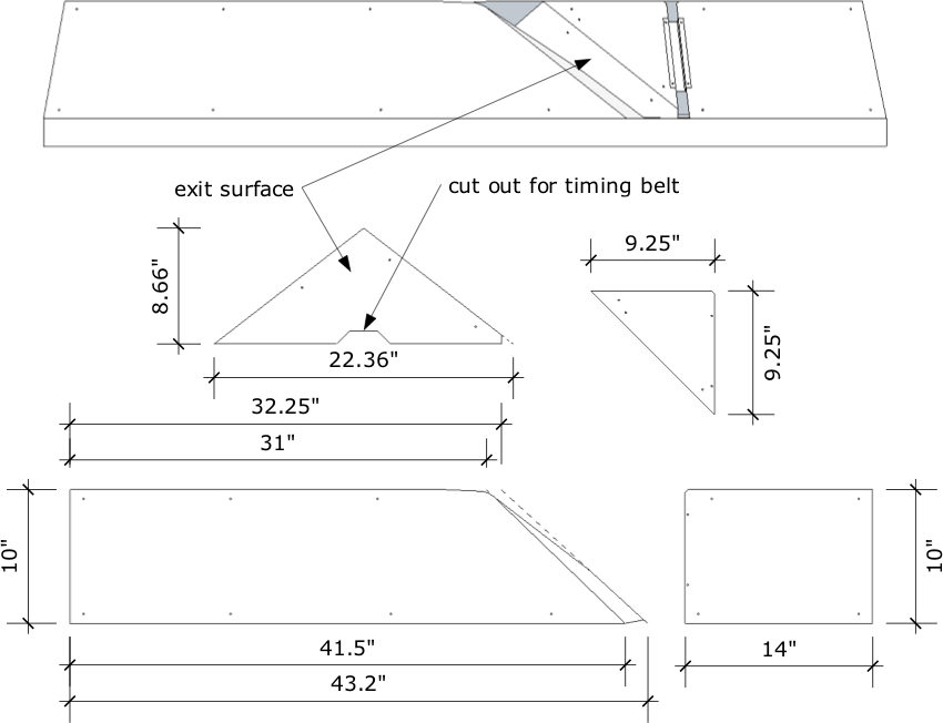
Page turning channel
The length of the page turning channel, between the two points shown, must be longer than the spine of the book. Otherwise, the turned page will be twisted or torn as it passed through the channel. The tiny gap in the middle between the two support surfaces must be wide enough for the turned page to pass through easily, and the support surfaces must be stiff enough not to flex under the weight of the book and close the gap.
Similarly, any torsion in the base may cause the gap to close, so the base must be stiff enough to prevent this.
Exit surface
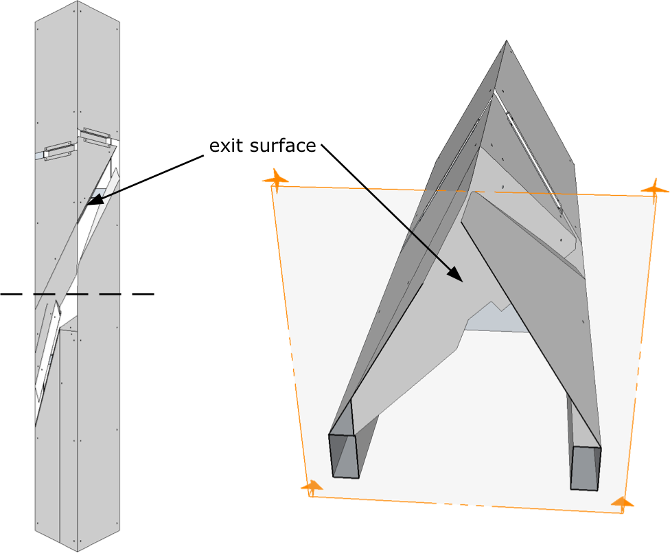
The exit surface is mounted vertically inside the page turning channel, and guides the turned page out of the channel and on to the rest of the pages. The surface is mounted along a diagonal and must have a shallow angle to gradually guide the turned page out of the channel. If the angle is too steep, then the turned page may not line up with the rest, and become folded as it leaves the channel.
Saddle friction
For the saddle to slide easily over the machine, its weight is supported by low-friction HDPE inserts in the top corner of the saddle, which rides along the apex of the machine. The angle of the bend in the saddle can be slightly greater than 60 degrees to ensure that the saddle doesn’t clamp down on the sides. The bottom of the saddle is padded by foam board and covered in teflon tape to ride smoothly along the sides of the machine.
Most of the weight of the book itself is similarly supported near the binding, so in the prototype the apex of the machine is covered with teflon tape to reduce friction there. This friction may be less of an issue if the surfaces are made of stainless steel instead of aluminum.
Saddle clamps
The lower saddle clamps help support the weight of the book when most of the pages are to one side. They are flat pieces of metal positioned at an upward angle, so that they provide the most support for thicker stacks of pages. To position the clamps before scanning, first place the book down with it open somewhere near the middle of the book. Then, adjust the clamps to be against the book on all sides (though not tightly). From that point on, the clamps will provide support to whichever side of the book has more pages.
Scan sensor mounting
The scan sensors were placed at the opposite end of the machine as the vacuum system, to avoid any possible distortion from the turning of the page. The two sensors are next to each other so they may scan at the same time, but are slightly offset in position so that the sensors can mounted be as close to the top edge of the machine as possible, and not interfere with each other.
To match their behavior in the commercial scanner, the sensors require a thickness of glass between the sensor and the paper. Glass was cut for the prototype to fit over each sensor, and glued in place.
Calibration
White strips of calibration paper are mounted along the underside of the saddle, and cover the scan sensors when the saddle is in the home position. The scanner driver calibrates to these strips at the beginning of each scan.
Break-beam sensor
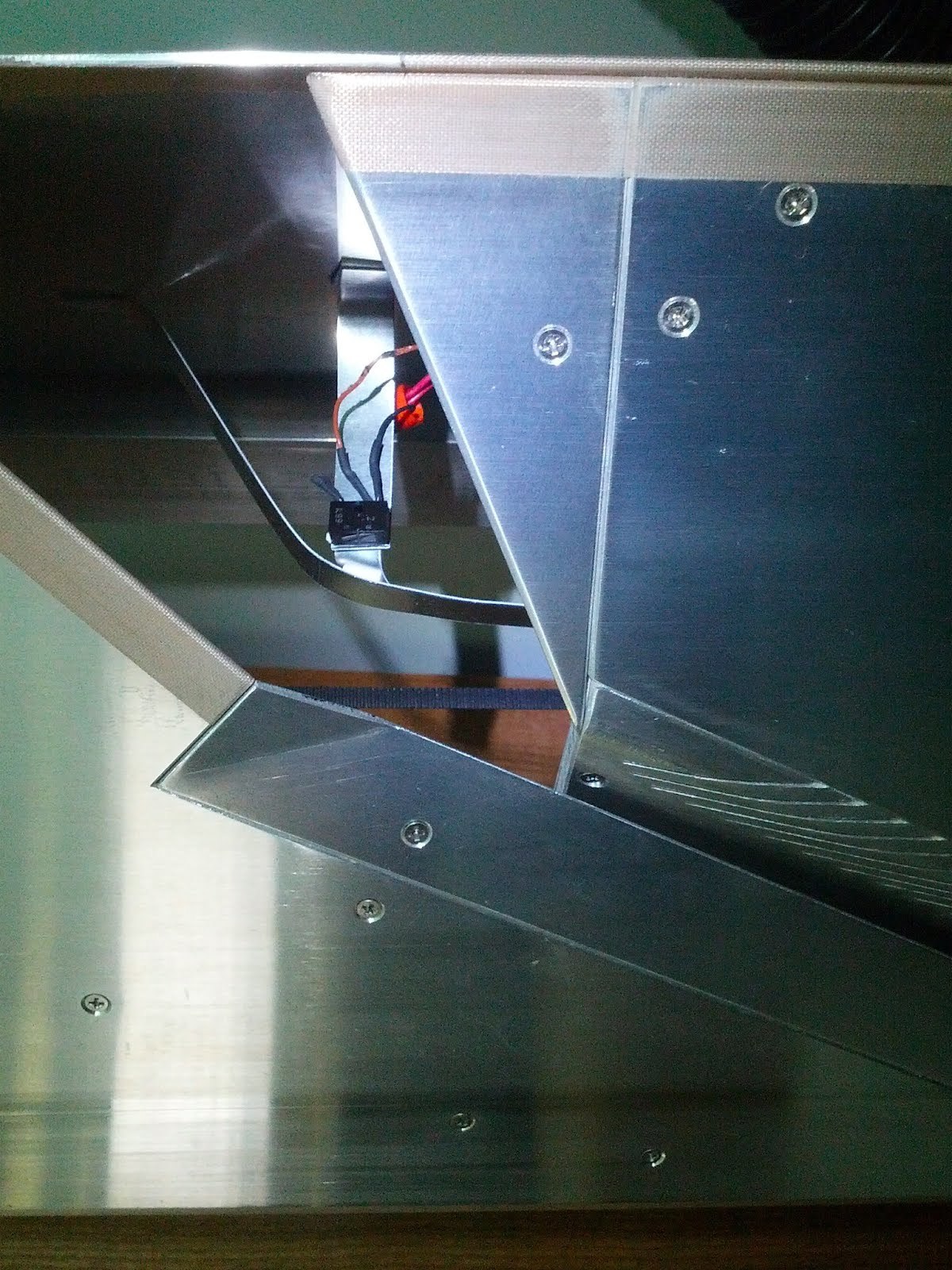
A break-beam sensor is mounted across the page turning channel. This sensor detects the presence of a page, and is connected directly to the motor’s microcontroller. If a page does not arrive exactly when expected, the machine stops immediately.
This allows the machine to detect (1) the end of the book, (2) when a page fails to turn, or (3) if pages fall into the channel when the book is moving back over the channel exit.
The detector is visible in the picture, with a guard rail to prevent pages from catching on it. The emitter is hidden behind the front surface, mounted near the end of the page separator.
Tips
Aluminum is not the best material for surfaces, as it leaves a small amount of residue on pages. We suggest stainless steel instead.
Many panels shown as separate pieces could instead be made out of a single sheet of metal bent into shape, to avoid seams.
Scanning speed is currently limited by the power of the motor used in the prototype. A more powerful motor could scan faster and handle heavier books. Also, a motor unit which provides load information would be useful for detecting errors.
The dimensions of the page turning channel and vacuum area can likely be adjusted to allow a wider range of book sizes. The sensor locations might also be adjusted to reduce the distance required for the book to travel, possibly increasing scanning rate.
Future versions
The shape of the page turning channel allows multiple channels to fit closely together, and a machine with two or more channels might scan more efficiently. A large machine with many such units could conceivably scan multiple books in parallel, for high volume tasks.
Appendix: Prototype dimensions and details
Note that these dimensions are very roughly specified, and intended only as a guideline.
Front surfaces
All surfaces in the prototype were made from .08” thick aluminum.
The small triangular piece is bent slightly inwards to prevent snags when the book is traveling to the right, and extends downwards to prevent snags on the slotted panel that fits below it.
Back surfaces
The right edge of the largest panel is bent inward to prevent pages from re-entering the page turning channel as the book passes back across the channel exit.
Interior surfaces
The page separator is mounted with a slight tilt relative to the front surface, so that the leading edge is recessed into the machine. The top-left corner of the page separator is bent slightly outward to become flush with the front surface.
The suction chamber is created by an interior panel with a 90-degree bend.
The long edge of the slotted panel is bent inward to create the curve that pulls away the page to be turned.
Base
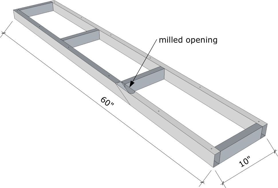
The base is made from 2”x1” rectangular aluminum tubing. Vacuum exhaust is routed along one side and out a milled opening underneath the vacuum exhaust guide. A small sloped insert within the base, next to the milled opening, guides the exhaust upward and prevents it from escaping out the other end of the base.
Saddle
The saddle is made from ¼” clear acrylic, cut into a frame shape and bent in the middle to a 60-degree angle.
Parts used in prototype
| quantity | part | description | link |
|---|---|---|---|
| 1 | Canon imageFORMULA DR-2510C Office Document Scanner | The prototype uses the scanning sensors and circuitry from this commercial scanner. | |
| 1 | MDrive23Plus Motion Control | This is the stepper motor with integrated microcontroller used to drive the saddle. | link |
| 12 Ft. | Trapezoidal-Tooth Neoprene Belting Mxl Trade Size, .080" Pitch, 1/4" Width | This is the timing belt used to drive the saddle. | link |
| 4 | Mxl and XL Series Timing-Belt Pulley 1/4" Belt Width, .685" OD, 20 Teeth | One of these pulleys is attached to the motor shaft, and the others are mounted with sleeve bearings. | link |
| 1 | Miniature 303 Stainless Steel Drive Shaft 1/8" OD, 6" Length | This is cut to form the shafts for the three passive pulleys. | link |
| 3 | SAE 863 Bronze Sleeve Bearing for 1/8" Shaft Diameter, 1/4" OD, 3/8" Length | Sleeve bearings are press-fit into the passive pulleys. | link |
| 6 | Black-Oxide Steel Set Screw Shaft Collar 1/8" Bore, 3/8" Outside Diameter, 1/4" Width | These collars hold the passive pulleys in place. | link |
| 1 each | Infrared LED Infrared phototransistor 160 ohm resistor |
Parts for the break beam sensor. | |
| 1 | Prototype development cable | Connects break beam sensor to microcontroller. | link |
| 1 each | USB to Serial Adapter 6 foot USB extension cable Unpowered USB hub |
Aggregates barcode wand, motor control, and imaging into a single USB connection. | |
| 1 | Vacuum cleaner with adjustable airflow Spare vacuum hose |
Powers pneumatic page turning. | |
| 1 | Symbol LS2208 Barcode Wand | Used to wand the book barcode. | link |
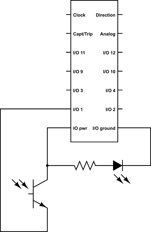
Sensor schematic
This schematic shows how the break-beam sensor connects to the I/O port on the MDrive23 motor.
Design document from http://code.google.com/p/linear-book-scanner/